Greetings, Lathe Ops, cutting
engineers, and aficionados of music recording and or
engineering:
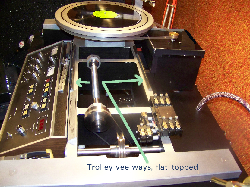
R ecently, we were discussing the bedways of the
Scully lathes. I like how the trolley wheels ride on flat
surfaces that are claimed from the Aztec / Mayan pyramid-like
silhouette of the vee ways. In order to address a problem
with the Finish Cancel Trip signal (discussed below), I had
to remove the carriage. While it was off, I decided to do
a photo shoot to add to the
documentation on the ways.
As for the "ways" they made
them, these Scully pyramids "boogie" "mesas." Notice,
also, how the wheel at the tail end of the bed goes. " \_/," so as
to hug, with discouraged, but not disallowed, wiggle, providing
the rudder of the carriage an even footing
These Finish Cancel Trip micro-switches were
nearly boggling me mind, for a while. I know
that they say to check the connector, but it was the last
connector I'd ever had thought of, since it is normally hidden,
seldom disturbed, and was still tightly connected. The
micro-switches are bundled in a snake, which mates with another
section of snake, under the lathe bed. One of the pins on
the male connector, there, was invisibly oxidized enough to sort
of fall asleep, electrically (or that's what I've decided).
Once I unplugged that connector and replugged it, together, it
worked. I put some Caig DeOxit on there and plug-cycled it
about 20 times. Have been doing contact maintenance on all
the surfaces. Alas, Mr. Grundy did not restore this vintage
machine before I bought it. (Note: Caig D5 and Gold
(follow-up) done to all contacts, September 2014, with immediate
improvement in logic supply efficiency).
Before I found the solution, I
naturally checked every transistor and integrated circuit on all
seven boards.
The micro-switch showed
continuity when tripped. The wire ("W") on the pin of the
turntable speed selector switch,
which is designated for the
12" Finish Cancel Trip,* was showing continuity with its
destinations in the card cage and
with ground, when
selected.
Yes, I did have the ability
to do manual mode lock-out cutting at the end of a side, but when
the thing is working and is
automated to precise RIAA
disc-diameter specification/suggestions, without the operator
breaking more of a sweat than,
say, doing the work
involved in selecting a side on a juke box, I could not rest until
the answer was found and the problem
solved. (rest,
resumed)
* Finish Cancel Trip
happens when the carriage has been fed far enough to the left that
the micro-switch, which causes the
Feed to be canceled,
without stopping the turntable or lifting the head before a
complete revolution and a half has occurred,
thereby creating a locked
groove at the end of side, is tripped.
I was concerned about the amount
of turntable runout, and, when the tightening and loosening of the
platter hold down bolts was insufficient to tame the variance of
flatness during the revolution of the platter, I resolved to
check the isolation mount posts for their correct
adjustment. Fortunately, only one of them was not
correct. One can loosen a nut under the steel
weldment and, after removing the aluminum shroud, rotate the
isolation mount post to raise or lower the given corner of the
A-table.
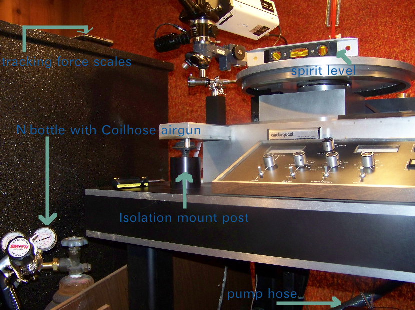
Bottle regs: "Lefty
Loose and Righty Tight," for off.....
Normally, two assistants
are required so that each end of the A-table can be supported
while the spirit level is made to
rest horizontally and you
rotate the coffee mug-shaped post to make the necessary
adjustment. Then you tighten the nut,
underneath the weldment,
and replace the shroud...
In this case, the other
posts were correct, already, so I was just able to rotate it by
myself, with only some difficulty -
"sweat equity?," but with
the WPI (work progress indicator) that the air bubble had become,
once again, centered throughout
the turntable
revolution.
It is now holding that corner up flat, and the depth feeler is showing
the runout to be, once again, reasonably in spec. The
goal is +/- 1 mil during one slow
revolution (by hand).

While doing the photo shoot, I thought I'd
document the captive suction mounting vacuum
line.
The original version of the LS-76 was like the Neumann VMS lathes
which have a vacuum tower above the table, with a hose terminating
in a chuck which is put on top of the spindle, once the blank
workpiece is in place. This causes vacuum pressure to
be an invisible mandrel,
using the system of air canals that provide suction mounting
through holes in the platter. There was no edition of
the LS-76 manual which
demonstrated the captive vacuum line, but it is in this Scully
(#656), and also, at least, on #660.
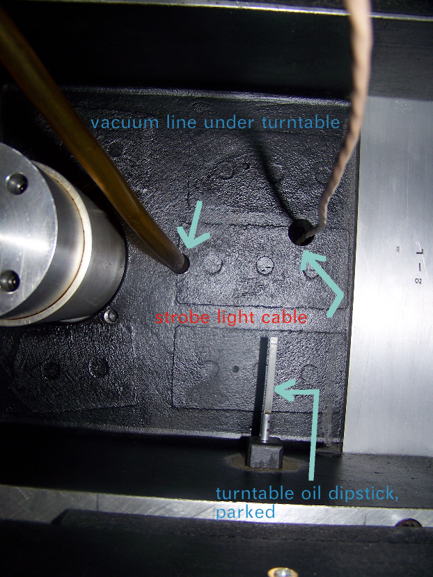
...and, topside (shown,
below - taken while platter was removed, of course):

There are three threaded holes on the top of the turntable that
the platter bolts onto. The dipstick hole is just showing
over the rear edge of the spindle.
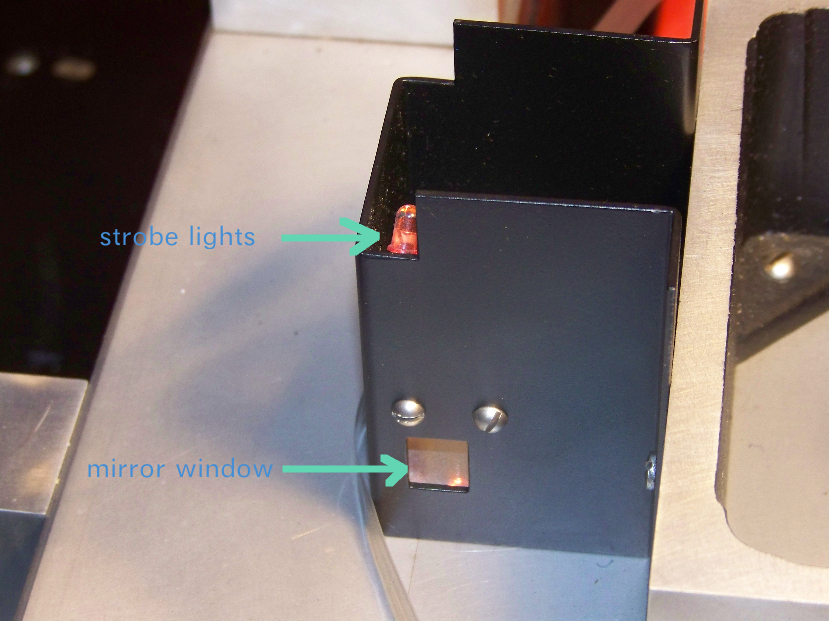
Here's a view (below) of the strobe light mirror
window, next to the turntable.
The clear mylar belt used for turntable rim drive is resting next
to it. The top of this housing is normally covered by
the platter, and the light bulbs are thereby
concealed. But the little window looks in on a tilted
mirror, which reflects the light
display from above for non-glaring optical confirmation of steady
revolution at the selected speed. This is rather like a
periscope.
The article, only half-jokingly titled, He Who Lathes Best,
mentions that Scully made a lathe for the Navy to use in a
submarine.
Perhaps there was some cross-polination of design and engineering,
over the years, between Westrex, Scully, The Armed Forces, and
Tom Dowd. One can dream, can't he?